LAB-GSS
Grid-Tied Bidirectional DC Supply
LAB-GSS
Grid-Tied Bidirectional DC Supply
The modular LAB-GSS's extensive feature set includes programmable PID parameters and an in-built 8 channel recording scope.
| Min | Max | |
|---|---|---|
| Power: | 0 to 20kW | 0 to 2MW This maximum is achieved by using units in master-slave. |
| Voltage: | 0 to 65VDC | 0 to 1500VDC This maximum is achieved by using units in master-slave. |
| Current: | 0 to ±40A | 0 to ±38400A This maximum is achieved by using units in master-slave. |
| Standard Control: | Analogue, RS-232 |
|---|---|
| Optional Control: | HMI, CAN, Ethernet, IEEE 488.2, Optolink, RS-422, USB |
or call 01246 452909 to discuss this product
Product Information
The LAB-GSS is able to operate as either a DC source or an electronic DC load. This integrated approach features high dynamics enabling the user to switch quickly between quadrants.
An extensive feature set includes an inbuilt 8 channel recording scope, adjustable internal resistance, RS‑232 and analogue interfaces. An optional embedded function generator can be fitted, which allows virtually any complex DC waveform to be created.
- Stackable up to 1500V/Very High Powers
- Mains Regeneration of the DC Sink Energy
- Excellent GUI with Built-in Scope Function
- Function Generator with V/I Capability
- Battery Cycling and Emulation Software
- Adjustable Internal Resistance
Technical Specifications
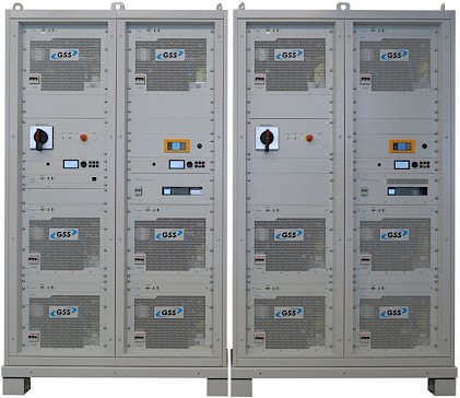
Modularity (Master/Slave)
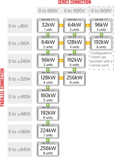 Up to 64 LAB-GSS modules can be arranged in series, parallel or matrix array configurations. Each module is able to operate independently, so that systems can be reconfigured, expanded or broken up as needs dictate. Inbuilt system comms allow users to switch between various set-ups.
Operating Ranges and Features
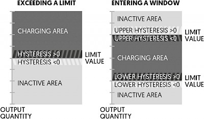 The VLS allows the LAB-GSS's output relays to be activated automatically when specific output values are met, protecting the DUT from any damaging charge conditions. Output voltage, current and power values which exceed or fall below a given limit or operating window can be programmed to trigger the relays. Active and inactive areas of operation are defined by a limit value, hysteresis value or a directional designator for the hysteresis.
Operating Modes
Input
Interfaces and Control
Software/Soft Tools
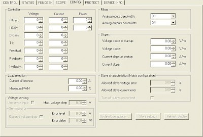 All LAB-GSS units come with a simple and intuitive TopControl operating GUI as standard. Live values of the power system are displayed graphically along with any warning and error messages. The software provides a variety of second level parameters, ideal for users who like to optimise their test processes. In standard user mode the operator can remotely program set values, enable voltage output as well as the ability to analyse different variables including set and actual values via the integrated scope.
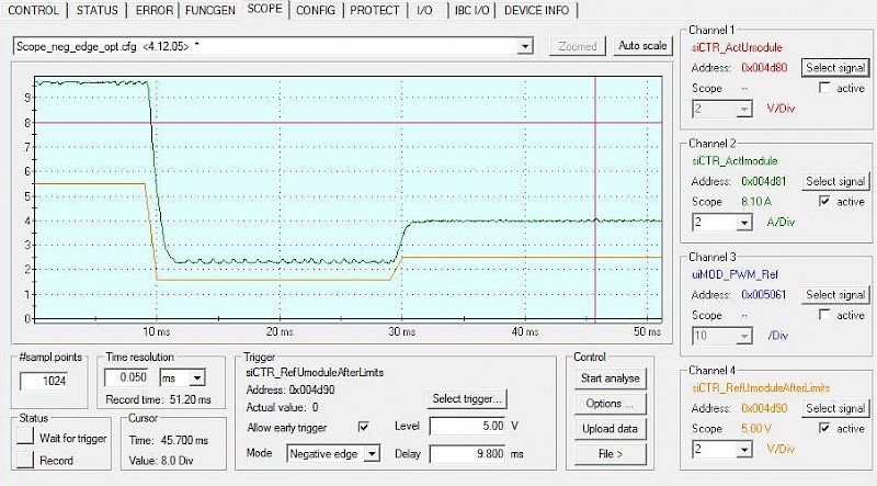
APPLICATION SPECIFIC GUIs
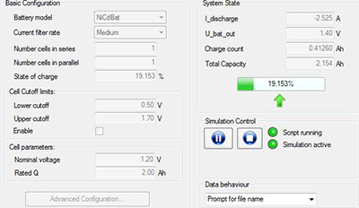 BatSim provides a convenient method for the LAB-GSS to emulate different sized battery stacks. Nearly all relevant electrical characteristics are programmable, including the number of cells, energy capacity, cut off limits, chemistry type and nominal voltage.
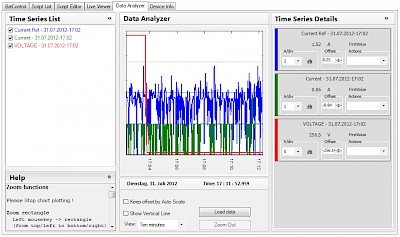 Drive cycle tests can be implemented using BatControl. Previous data obtained from a test track can be imported and recreated, allowing the LAB-GSS to simulate a real world driving test inside a lab environment. Battery and capacitor charge/discharge profiles can also be implemented through the GUI.
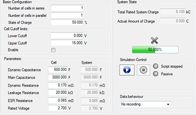 The bidirectional characteristics of a real capacitor stack can be emulated when CapSim is installed with LAB-GSS modules. Number of cells in series/parallel, state of charge, cell cut off limits, dynamic capacitance and resistance are programmable.
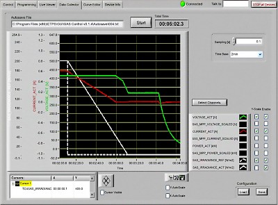 SASControl software has all EN 50530 tests pre-installed. The GUI allows users to edit irradiance, temperature and amplitude values. Previous tests have been conducted using over 400,000 individual data points, with more possible.
Safety and Protection
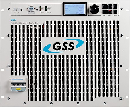
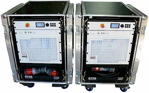
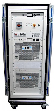
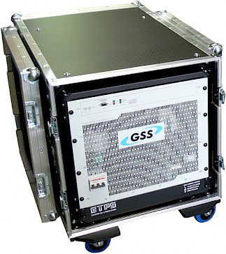
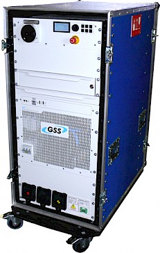
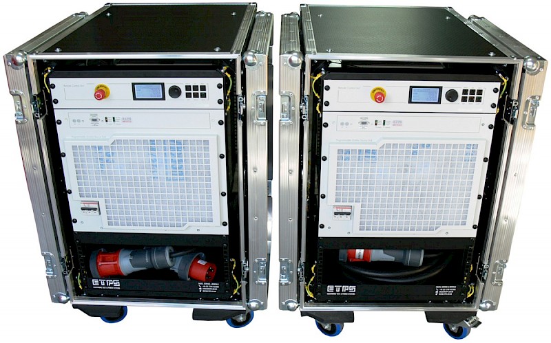
Mechanical
Form Factor and Enclosures
Rental Systems
Product Applications
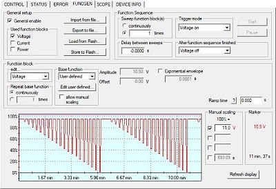 65V modules can perform a number of ISO 16750-2 tests. The optional embedded function generator allows the system to implement the voltage/time relationships which many of the strict standards require. Specific Tests which can be performed include:
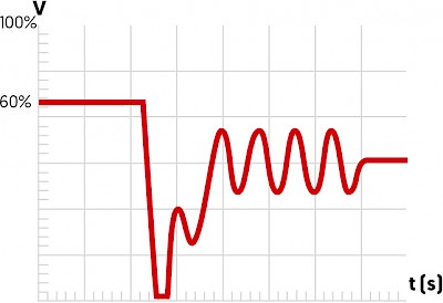 Electrical components within a vehicle's subsystem must be able to withstand a wide range of input voltage surges and drops during a start-up. The LAB-GSS can accurately recreate these conditions within a lab environment. This increases reproducibility and accuracy of results when compared to using real batteries.
 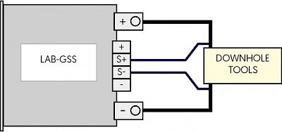 Applications with long load lines often suffer from unintended voltage drops, such as downhole tools used in hydrocarbon exploration. The LAB-GSS's sense plus allows voltage drops to be compensated for throughout the entire length of a load line. This feature is also ideal for powering subsea devices.
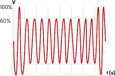 In electronic systems sudden voltage interruptions may cause unexpected behaviour. Supply line disturbances may have several causes, including an additional switch on of large capacitive loads parallel to the supply line or a short circuit caused by loads sharing the supply. The LAB-GSS can generate many complex DC waveforms to test devices under realistic conditions to identify any potential issues.
Selection Table
65V Module Configurations
| Part Number |
Nominal Power | Source Voltage Q1 | Sink Voltage Q4 | Current Range | |
|---|---|---|---|---|---|
| LAB-GSS 20-65 | 20kW | 0 to 65VDC | 6 to 65VDC | 0 to ±385A | Add |
| LAB-GSS 32-65 | 32kW | 0 to 65VDC | 6 to 65VDC | 0 to ±600A | Add |
| LAB-GSS 20-65-2 | 40kW | 0 to 130VDC | 6 to 130VDC | 0 to ±770A | Add |
| LAB-GSS 32-65-2 | 64kW | 0 to 130VDC | 6 to 130VDC | 0 to ±1200A | Add |
| LAB-GSS 32-65-3 | 96kW | 0 to 195VDC | 6 to 195VDC | 0 to ±1800A | Add |
| LAB-GSS 32-65-4 | 128kW | 0 to 260VDC | 6 to 260VDC | 0 to ±2400A | Add |
| LAB-GSS 32-65-8 | 256kW | 0 to 520VDC | 6 to 520VDC | 0 to ±4800A | Add |
130V Module Configurations
| Part Number |
Nominal Power | Source Voltage Q1 | Sink Voltage Q4 | Current Range | |
|---|---|---|---|---|---|
| LAB-GSS 20-130 | 20kW | 0 to 130VDC | 12 to 130VDC | 0 to ±192A | Add |
| LAB-GSS 32-130 | 32kW | 0 to 130VDC | 12 to 130VDC | 0 to ±308A | Add |
| LAB-GSS 20-130-2 | 40kW | 0 to 260VDC | 12 to 260VDC | 0 to ±384A | Add |
| LAB-GSS 32-130-2 | 64kW | 0 to 260VDC | 12 to 260VDC | 0 to ±616A | Add |
| LAB-GSS 32-130-3 | 96kW | 0 to 390VDC | 12 to 390VDC | 0 to ±924A | Add |
| LAB-GSS 32-130-4 | 128kW | 0 to 520VDC | 12 to 520VDC | 0 to ±1232A | Add |
| LAB-GSS 32-130-8 | 256kW | 0 to 1040VDC | 12 to 1040VDC | 0 to ±2464A | Add |
400V Module Configurations
| Part Number |
Nominal Power | Source Voltage Q1 | Sink Voltage Q4 | Current Range | |
|---|---|---|---|---|---|
| LAB-GSS 20-400 | 20kW | 0 to 400VDC | 50 to 400VDC | 0 to ±63A | Add |
| LAB-GSS 32-400 | 32kW | 0 to 400VDC | 50 to 400VDC | 0 to ±100A | Add |
| LAB-GSS 20-400-2 | 40kW | 0 to 800VDC | 50 to 800VDC | 0 to ±126A | Add |
| LAB-GSS 32-400-2 | 64kW | 0 to 800VDC | 50 to 800VDC | 0 to ±200A | Add |
| LAB-GSS 32-400-3 | 96kW | 0 to 1200VDC | 50 to 1200VDC | 0 to ±300A | Add |
| LAB-GSS 32-400-4 | 128kW | 0 to 1500VDC | 50 to 1500VDC | 0 to ±400A | Add |
| LAB-GSS 32-400-8 | 256kW | 0 to 1500VDC | 50 to 1500VDC | 0 to ±800A | Add |
500V Module Configurations
| Part Number |
Nominal Power | Source Voltage Q1 | Sink Voltage Q4 | Current Range | |
|---|---|---|---|---|---|
| LAB-GSS 20-500 | 20kW | 0 to 500VDC | 40 to 500VDC | 0 to ±50A | Add |
| LAB-GSS 32-500 | 32kW | 0 to 500VDC | 40 to 500VDC | 0 to ±80A | Add |
| LAB-GSS 20-500-2 | 40kW | 0 to 1000VDC | 40 to 1000VDC | 0 to ±100A | Add |
| LAB-GSS 32-500-2 | 64kW | 0 to 1000VDC | 40 to 1000VDC | 0 to ±160A | Add |
| LAB-GSS 32-500-3 | 96kW | 0 to 1500VDC | 40 to 1500VDC | 0 to ±240A | Add |
| LAB-GSS 32-500-4 | 128kW | 0 to 1500VDC | 40 to 1500VDC | 0 to ±320A | Add |
| LAB-GSS 32-500-8 | 256kW | 0 to 1500VDC | 40 to 1500VDC | 0 to ±640A | Add |
600V Module Configurations
| Part Number |
Nominal Power | Source Voltage Q1 | Sink Voltage Q4 | Current Range | |
|---|---|---|---|---|---|
| LAB-GSS 20-600 | 20kW | 0 to 600VDC | 50 to 600VDC | 0 to ± 40A | Add |
| LAB-GSS 32-600 | 32kW | 0 to 600VDC | 50 to 600VDC | 0 to ±66A | Add |
| LAB-GSS 20-600-2 | 40kW | 0 to 1200VDC | 50 to 1200VDC | 0 to ±80A | Add |
| LAB-GSS 32-600-2 | 64kW | 0 to 1200VDC | 50 to 1200VDC | 0 to ±132A | Add |
| LAB-GSS 32-600-3 | 96kW | 0 to 1500VDC | 50 to 1500VDC | 0 to ±198A | Add |
| LAB-GSS 32-600-4 | 128kW | 0 to 1500VDC | 50 to 1500VDC | 0 to ±264A | Add |
| LAB-GSS 32-600-8 | 256kW | 0 to 1500VDC | 50 to 1500VDC | 0 to ±528A | Add |
Frequently asked questions
Can't find what you're looking for? Ask us a question
Please fill out the form below and we will get back to you as soon as possible with an answer to your question.