G5-BATSIM
High Voltage Modular Battery Emulators
G5-BATSIM
High Voltage Modular Battery Emulators
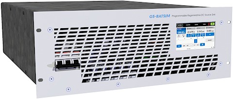
G5-BATSIM systems are provided with an advanced GUI to accurately emulate batteries. Modules are stackable to 3kV/6MW with mains recycling.
| Min | Max | |
|---|---|---|
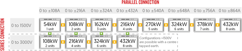
| Power: | 0 to 18kW | 0 to 6MW This maximum is achieved by using units in master-slave. |
| Voltage: | 0 to 500VDC | 0 to 3000VDC Configurations >1500V are possible with a centre tapped earth. |
| Current: | 0 to ±54A | 0 to ±19440A This maximum is achieved by using units in master-slave. |
| Standard Control: | Analogue, Ethernet, USB |
|---|---|
| Optional Control: | Touchscreen HMI, CAN, EtherCAT |
or call 01246 452909 to discuss this product
Product Information
G5-BATSIM systems are provided with an advanced GUI to accurately emulate the electrical characteristics of batteries. Modules are stackable to 3kV/6MW with mains recycling.
Nearly all relevant electrical characteristics are programmable, including the number of cells, energy capacity, cut off limits, chemistry type and nominal voltage. Each power dense module has an extensive feature set which includes programmable PI parameters and an inbuilt 8 channel recording scope. Adjustable power and resistance limits are provided. Optional remote control interfaces are available including high-speed CAN and a touchscreen HMI.
- Industry Leading 50μs Response Times
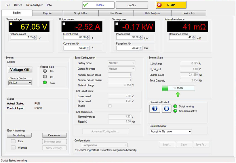
- Advanced Battery Emulation Software
- Two Current Ranges for Higher Accuracy
- ± Voltage in Series M/S with Midpoint Earth
- Sink/Source Voltages up to 3000V
- Programmable Ripple up to 10kHz
Technical Specifications
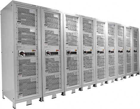
Modularity (Master/Slave)
Operating Ranges and Features
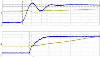 A current step between 90% sourcing to 90% sinking current can be as quick as 50µs, enabling high speed drives to be supplied. Advanced users have access to the controller settings enabling the response to be optimised for particular loads. The example shows a current step through quadrants.
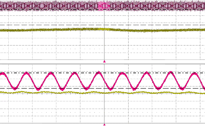 By utilising the optional embedded function generator the user can set a current ripple at up to 10kHz. The magnitude can be up to 5% of the nominal system current. Depending on the impedance of the DUT the resulting voltage ripple can be calculated. The below example shows a 10kHz ripple generated using the function generator of the G5-BATSIM. A peak to peak current of 8A has been superimposed on a current of 100A. Alternatively, a ripple can be implemented from an external waveform generator via the analogue interface using a proportional 0-10V signal.
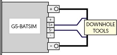 Sense plus terminals are built into the G5-BATSIM for the connection of sense wire which compensates for voltage drops in the load lines. This has a number of advantages over traditional sense. It is permitted to interrupt the load line during operation (voltage on). The maximum voltage drop compensation is adjustable. The voltage difference between G5-BATSIM output and sensing point is monitored. If a set limit is exceeded, the G5-BATSIM unit shuts off. This is particularly useful for applications with long cables often prone to unwanted voltage drops.
 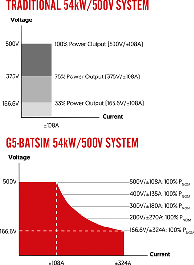 Every G5-BATSIM features an autoranging output. This allows many more voltage/current combinations at nominal power than a traditional bidirectional DC power system. An example of the difference is shown below using a G5-BATSIM 54-500-324.
Operating Modes
Input
Interfaces and Control
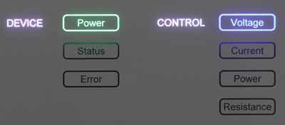 As standard the front panel has backlit indicators which illuminate to show which control mode the power system is operating in (CV, CC, CP, CR). When the G5-BATSIM has been successfully energised, the corresponding power light illuminates green to indicate this. An illumination is also provided to visually warn users of any status (yellow) or error (red) message.
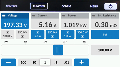 The optional HMI provides a simple and intuitive way of control and measurement via a touchscreen panel. Users can directly access features such as the system's protections, warnings/errors and optional function generator without the use of a computer. A user defined passcode can be set to lock the touch screen, which prevents unauthorised access. When selected, the HMI replaces the front panel indicator.
Software/Soft Tools
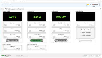
 Standard G5.Control GUI
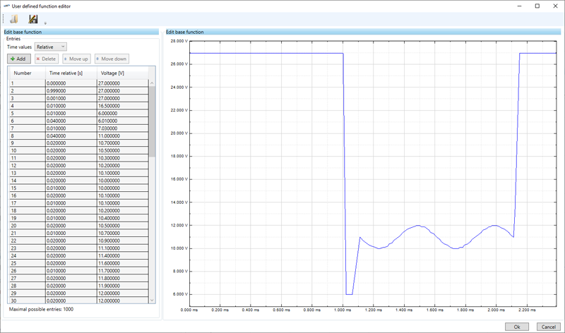
OPTIONAL APPLICATION GUIs
Safety and Protection
Mechanical
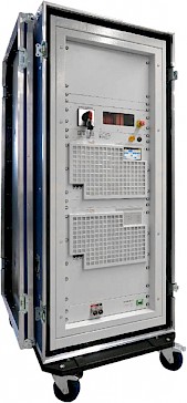
 The G5-BATSIM modules are designed to be operated within a clean laboratory environment. If there is the possibly that the environment will be less clean, then the optional front panel frame and air filter arrangement offer some additional protection. The standard filter material is rated in class G3. This class is effective at trapping a high proportion (90%) of particles ≥10um according to EN 779.
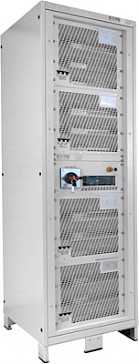
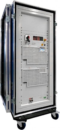
 Form Factor and Enclosures
Rental Systems
Selection Table
| Part Number |
Nominal Power | Source Voltage Q1 | Sink Voltage Q4 | Current Range | Internal Resistance Range | |
|---|---|---|---|---|---|---|
| G5-BATSIM 18-500-108 | 18kW | 0 to 500VDC | 3 to 500VDC | 0 to ±108A | 0 to 5000Ω | Add |
| G5-BATSIM 18-1000-54 | 18kW | 0 to 1000VDC | 5 to 1000VDC | 0 to ±54A | 0 to 18000Ω | Add |
| G5-BATSIM 27-500-162 | 27kW | 0 to 500VDC | 3 to 500VDC | 0 to ±162A | 0 to 3000Ω | Add |
| G5-BATSIM 27-1500-54 | 27kW | 0 to 1500VDC | 8 to 1500VDC | 0 to ±54A | 0 to 27000Ω | Add |
| G5-BATSIM 36-500-216 | 36kW | 0 to 500VDC | 3 to 500VDC | 0 to ±216A | 0 to 2500Ω | Add |
| G5-BATSIM 36-1000-108 | 36kW | 0 to 1000VDC | 5 to 1000VDC | 0 to ±108A | 0 to 10000Ω | Add |
| G5-BATSIM 54-500-324 | 54kW | 0 to 500VDC | 3 to 500VDC | 0 to ±324A | 0 to 1500Ω | Add |
| G5-BATSIM 54-1000-162 | 54kW | 0 to 1000VDC | 5 to 1000VDC | 0 to ±162A | 0 to 6000Ω | Add |
| G5-BATSIM 54-1500-108 | 54kW | 0 to 1500VDC | 8 to 1500VDC | 0 to ±108A | 0 to 14000Ω | Add |
Frequently asked questions
Can't find what you're looking for? Ask us a question
Please fill out the form below and we will get back to you as soon as possible with an answer to your question.