G5-RSS
HV POWER RECYCLING LOADS UP TO 324kW

G5-RSS
HV POWER RECYCLING LOADS UP TO 324kW
With the ability to source or sink DC power up to 2000V, the G5-RSS is ideal for testing and emulating energy storage devices.
| Min | Max | |
|---|---|---|
| Power: | 0 to 54kW | 0 to 324kW |
| Voltage: | 5 to 1000VDC | 10 to 2000VDC Configurations >1500V are possible with a centre tapped earth. |
| Current: | 0 to 162A | 0 to 972A |
| Standard Control: | Model Specific |
|---|---|
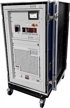
| Enclosure: | Flightcase |
or call 01246 452909 to discuss this product
Product Information
With the ability to source or sink DC power up to high voltage and currents, the G5-RSS is ideal for cycling and emulating energy storage devices.
Each power dense module has an extensive feature set which includes programmable PID parameters and an inbuilt 8 channel recording scope. Adjustable power and resistance limits are provided. Analogue, ethernet, USB and high-speed CAN interfaces are provided with each system. The G5-RSS features an autoranging output, which allows for many more V/I combinations at nominal power. Modules are fitted into flight cases which feature isolation monitoring and an emergency stop.
- Two Current Ranges for Higher Accuracy
- Battery Cycling and Emulation Software
- Function Generator with V/I Capability
- Programmable Ripple up to 10kHz
- Sink/Source Voltages up to 2000V
- Ultra-Fast Dynamic Behaviour
Technical Specifications
Modularity (Master/Slave)
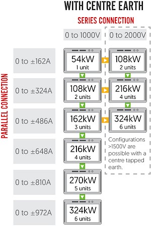 Up to six G5-RSS 54kW/1000V modules are available in our rental range. These can be arranged in series or parallel configurations. Outputs up to 2000V are possible if you can connect the modules around a centre earth. Each module is able to operate independently, with inbuilt system comms allowing users to switch between various set-ups.
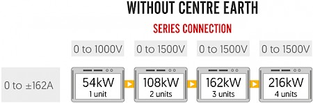
Operating Ranges and Features
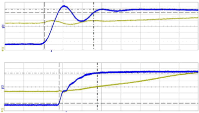 A current step between 90% sourcing to 90% sinking current can be as quick as 50µs, enabling high speed drives to be supplied. Advanced users have access to the controller settings enabling the response to be optimised for particular loads. This example shows a current step through quadrants. The upper trace shows the current transition is achieved in 50µs with a small overshoot before settling. The lower plot shows a more regulated response within 200µs. Voltage typically takes 100µs to recover within 0.5% of the set value. In multi-module systems the communication time between modules need to be considered.
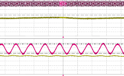 By utilising the embedded function generator the user can set a current ripple at up to 10kHz. The magnitude can be up to 5% of the nominal system current. Depending on the impedance of the DUT the resulting voltage ripple can be calculated. The below example shows a 10kHz ripple generated using the function generator of the G5-RSS. A peak to peak current of 8A has been superimposed on a current of 100A. Alternatively, a ripple can be implemented from an external waveform generator via the analogue interface using a proportional 0-10V signal.
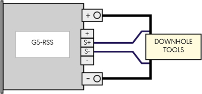 Sense plus terminals are built into the G5-RSS for the connection of sense wire which compensates for voltage drops in the load lines. This has a number of advantages over traditional sense. It is permitted to interrupt the load line during operation (voltage on). The maximum voltage drop compensation is adjustable. The voltage difference between G5-RSS output and sensing point is monitored. If a set limit is exceeded, the G5-RSS unit shuts off. This is particularly useful for applications with long cables often prone to unwanted voltage drops.
 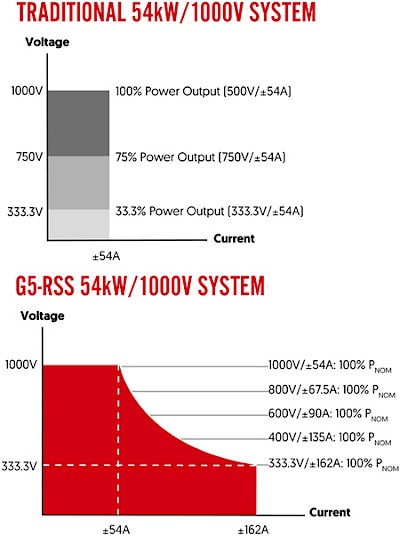 Every G5-RSS features an autoranging output. This allows many more voltage/current combinations at nominal power than a traditional bidirectional DC power system. An example of the difference is shown below using a single G5-RSS 54-1000-162 module.
Operating Modes
Input
Interfaces and Control
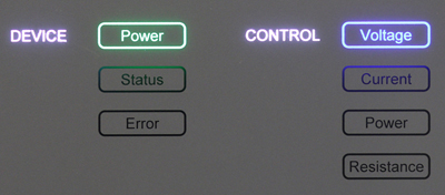 As standard the front panel of each modules has backlit indicators which illuminate to show which control mode the power system is operating in (CV, CC, CP, CR). When the G5-RSS has been successfully energised, the corresponding power light illuminates green to indicate this. An illumination is also provided to visually warn users of any status (yellow) or error (red) message.
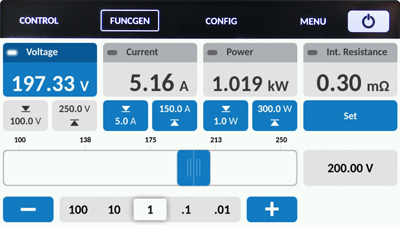 The HMI at cabinet level provides a simple and intuitive way of control and measurement via a touchscreen panel. Users can directly access features such as the system's protections, warnings/errors and function generator without the use of a computer. A user defined passcode can be set to lock the touch screen, which prevents unauthorised access. When selected, the HMI replaces the front panel indicator.
Software/Soft Tools
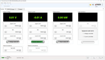 All G5-RSS units come with a simple and intuitive G5.Control operating GUI as standard. Live values of the power system are displayed graphically along with any warning and error messages. The software provides a variety of second level parameters, ideal for users who like to optimise their test processes. In standard user mode the operator can remotely program set values, enable voltage output as well as the ability to analyse different variables including set and actual values via the integrated scope.
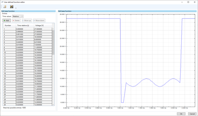 Complex DC waveforms can be implemented through the embedded function generator. The highly programmable nature of the function generator allows users to plot out exact waveforms. This is often advantageous when emulating a power device with a very specific behaviour profile. For example, when quality testing fuel cell powered equipment, the specific behaviour of a discharging fuel cell can be programmed and replicated.
APPLICATION SPECIFIC GUIs
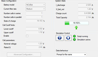 BatSim is a battery emulation GUI for use with G5-RSS power systems. The GUI allows the power systems to simulate real world behaviour of a battery pack.
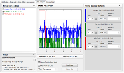 Drive cycle tests can be implemented using BatControl. The GUI’s main screen provides an overview of the main test values for all BatControl operations. Live data from the connected power system is displayed, and setting/adjustment of primary values is possible.
 Form Factor and Enclosures
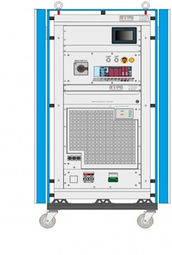 A series of cabinets are used to make deployment of G5-RSS rental modules simpler, quicker and safer. Among the cabinet safety features which most of the modules are installed in is a status indicator that alerts users of any residual energy on the DC link that is greater than 30V. This operates even if the mains power is turned off. Another indicator assesses the quality and correct rotation of the AC input voltage and illuminates if correct.
New Systems
Product Applications
Selection Table
| Part Number |
Nominal Power | Source Voltage Q1 | Sink Voltage Q4 | Current Range | Internal Resistance Range | |
|---|---|---|---|---|---|---|
| G5-RSS 54-1000-162-r | 54kW | 0 to 1000VDC | 5 to 1000VDC | 0 to ±162A | 0 to 12346mΩ | Add |
| G5-RSS 108-1000-324-r | 108kW | 0 to 1000VDC | 5 to 1000VDC | 0 to ±324A | 0 to 6173mΩ | Add |
| G5-RSS 108-2000-162-r | 108kW | 0 to 2000VDC | 10 to 2000VDC | 0 to ±162A | 0 to 24692mΩ | Add |
| G5-RSS 162-1000-486-r | 162kW | 0 to 1000VDC | 5 to 1000VDC | 0 to ±486A | 0 to 4114mΩ | Add |
| G5-RSS 162-1500-162-r | 162kW | 0 to 1500VDC | 15 to 1500VDC | 0 to ±162A | 0 to 37038mΩ | Add |
| G5-RSS 216-1000-648-r | 216kW | 0 to 1000VDC | 5 to 1000VDC | 0 to ±648A | 0 to 3086mΩ | Add |
| G5-RSS 216-2000-324-r | 216kW | 0 to 2000VDC | 10 to 2000VDC | 0 to ±324A | 0 to 12346mΩ | Add |
| G5-RSS 270-1000-810-r | 270kW | 0 to 1000Vdc | 5 to 1000VDC | 0 to ±810A | 0 to 2469mΩ | Add |
| G5-RSS 324-1000-972-r | 324kW | 0 to 1000Vdc | 5 to 1000VDC | 0 to ±972A | 0 to 2057mΩ | Add |
| G5-RSS 324-2000-486-r | 324kW | 0 to 2000Vdc | 10 to 2000VDC | 0 to ±486A | 0 to 8230mΩ | Add |
Frequently asked questions
Can't find what you're looking for? Ask us a question
Please fill out the form below and we will get back to you as soon as possible with an answer to your question.